Testing MCP servers end-to-end on real hardware: a coax loopback found a bug
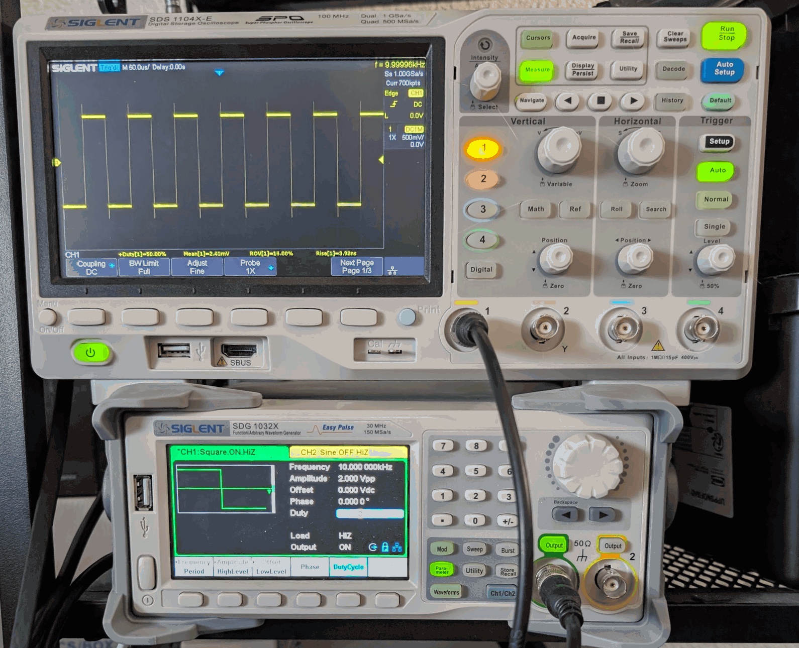
I have two MCP servers that let an AI assistant drive my bench instruments: one for a Siglent SDS1104X-E oscilloscope and one for a Siglent SDG1032X waveform generator. Over the last weeks both went through a security overhaul: stricter input checks, a query guard, connection allowlists, new release pipelines. Hundreds of tests pass. Each server also has a hardware check that runs its security probes against the real instrument.
None of that tells me whether they still work. When the generator server says “Basic wave configured”, that is the server’s opinion. When I ask the generator what it is set to, it repeats back what it was told. My unit tests check which bytes go to the instrument. Every one of those checks is the system describing itself. None of them proves that a 1 kHz sine actually leaves the output connector.
So I connected the two instruments with a coax cable and let one server check the other’s work. It found a bug my unit tests couldn’t find, because they had been written from the same documentation as the bug.
The setup
The generator’s CH1 output goes straight into the scope’s CH1 input: one BNC cable, no terminator. A script drives both servers through their MCP tools, exactly the way an AI client would:
flowchart LR
  T[Test script<br/>MCP client] -- "configure_basic_wave<br/>configure_output" --> G[siglent-sdg-mcp]
  G -- "SCPI" --> SDG[SDG1032X]
  SDG -- "coax" --> SDS[SDS1104X-E]
  T -- "scpi_query PAVA?<br/>get_waveform" --> S[siglent-sds-mcp]
  S -- "SCPI" --> SDS
For each signal, the script checks the result two independent ways:
- The scope’s own measurements. Frequency, peak-to-peak, mean and duty cycle, read with
C1:PAVA? FREQand friends through the read-onlyscpi_querytool.PAVA?reads a measurement without adding it to the scope’s display, so the test leaves no clutter behind. - My own analysis of the raw samples.
get_waveformdownloads the samples, and the script computes the same quantities itself: frequency from midpoint crossings, peak-to-peak, mean, time above the midpoint.
The two paths share the instrument but not the code. If the scope says 1000 Hz and my analysis of the downloaded samples says 1000 Hz, both the measurement and the download path are working.
The signals:
| Scenario | What it tests |
|---|---|
| Output off | The scope sees nothing: the baseline. |
| Sine, 1 kHz, 1 Vpp | The basics. |
| The same sine with +0.5 V offset | DC offset reaches the output, and the mean follows it. |
| Square, 10 kHz, 2 Vpp, 50 % duty | Waveform type, amplitude and duty cycle. |
| Sine, 100 kHz, 1 Vpp | A hundred times faster. |
| Output off again | The output really switches off. |
A test that switches on a real output
This test has physical side effects, which changes how you write it. The script:
- aborts before touching anything if either generator output is already on, because something on the bench may depend on it;
- sets the waveform first and switches the output on last;
- stays at 2 Vpp or below, with the generator’s load set to high impedance to match the scope’s 1 MΩ input;
- always switches the output off at the end, also after a failure or a Ctrl-C, and reads the state back to confirm it;
- saves every setting it changes on both instruments and restores them, then reads them back and compares.
That last point matters more than it sounds. A test that leaves the scope at 5 µs/div with a measurement stuck on the screen costs the next person ten minutes of confusion.
My first version of “always” wasn’t. An independent review of the script found two ways it could leave the output on without saying so:
- It only switched the output off at the end if switching it on had succeeded. But the generator’s ON command is fire-and-forget: it can reach the generator while the tool call itself fails, for example on a timeout. The cleanup now switches the output off whenever the test has touched the generator, whether or not the ON call reported success.
- Ctrl-C skipped the cleanup entirely. Worse, Ctrl-C in a terminal goes to the whole process group, so it also kills the two MCP servers the cleanup would have used. The first Ctrl-C now stops the test, and the cleanup starts fresh server sessions to switch the output off and restore everything. A second Ctrl-C quits at once, with a warning.
I tested the second one on the bench: a Ctrl-C in the middle of the square-wave scenario, with the output on. The cleanup switched it off, confirmed it, and restored both instruments.
First run: 35 of 37, and the test was wrong
Everything matched except the square wave. I asked for 2 Vpp, and the scope measured 2.6 V peak-to-peak.
The frequency was exact, the duty cycle was exactly 50 % and the mean was zero, so the generator wasn’t confused about the waveform. The scope’s overshoot measurement said about 14 %. A square wave has fast edges, and a coax cable going into a 1 MΩ input with no terminator rings on every edge. Peak-to-peak includes the ringing, so it was the wrong measurement, not the wrong signal.
For a square wave, the right measurement is amplitude, the flat top minus the flat bottom. The scope’s AMPL said 2.02 V. My own analysis, taking the median of the samples above and below the midpoint, said 2.00 V.
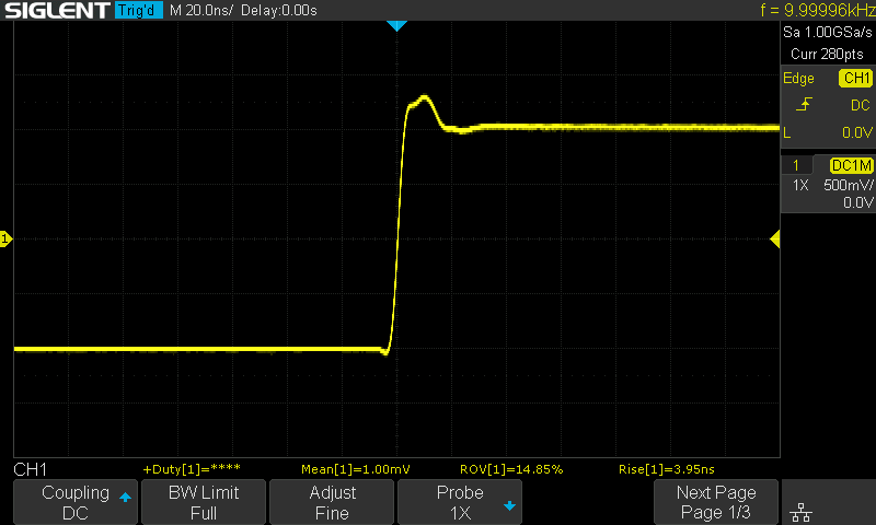 One rising edge at 20 ns/div, on the same signal later. Peak-to-peak counts the overshoot; amplitude measures the flat top and bottom.
A failing test is a question, not a verdict. This time the answer was “your test is measuring the wrong thing”.
The bug the cross-check found
With the square wave fixed, everything passed. But one number kept nagging me. The mean of a sine centred on zero, measured two ways:
Scope’s own MEAN | Mean of the downloaded samples | Difference | |
|---|---|---|---|
| Sine, 200 mV/div | 2.0 mV | 6.1 mV | 4.0 mV |
| Square, 500 mV/div | 6.0 mV | 16.8 mV | 10.8 mV |
Both within my tolerances, but the difference wasn’t random. The scope digitises each sample to an 8-bit code, and at 200 mV/div one code is 8 mV. At 500 mV/div it is 20 mV. Both differences were about half a code. Half a code is exactly what you get if every negative sample reads one code too high: half the samples of a centred signal are negative.
The scope sends each sample as a signed byte. The server converted it like this:
1
2
3
4
let codeValue = rawData[i];
if (codeValue > 127) {
  codeValue = codeValue - 255;
}
A signed byte needs 256, not 255: 0xFF is −1, not 0, and 0x80 is −128, not −127. With 255, every negative sample came out one code high, and 0xFF and 0x00 both decoded as zero.
The code didn’t invent the 255. Siglent’s programming guide says, word for word: “If the decimal is greater than ‘127’, it should minus 255.” The server followed the guide. So did the unit test, which asserted that byte 150 decodes to −105. The test passed because it was written from the same documentation as the bug. A simulator built from that guide would have agreed too. Only a measurement that doesn’t go through my code, the scope’s own MEAN, could disagree.
The fix is one line:
1
const codeValue = rawData[i] > 127 ? rawData[i] - 256 : rawData[i];
I added a check to the loopback script: at zero scope offset, the mean of the downloaded samples must agree with the scope’s MEAN within a quarter of a code. Then I put the old decoding back and ran it, to make sure the check could actually fail:
| Scenario | Old decoding | Fixed |
|---|---|---|
| Sine 1 kHz, 200 mV/div (limit 2 mV) | 3.9 mV apart, fail | 0.3 mV |
| Square 10 kHz, 500 mV/div (limit 5 mV) | 12.9 mV apart, fail | 0.8 mV |
| Sine 100 kHz, 200 mV/div (limit 2 mV) | 3.8 mV apart, fail | 0.2 mV |
The error was small, at most 4 % of a division per sample. It wouldn’t have changed anyone’s measurement in a way they would notice. That’s the point: it was too small to notice by eye and invisible to tests built from the same guide.
Why only at zero offset? With the scope’s offset at −0.5 V, the two means differed by 4.6 mV even after the fix. get_waveform applies the offset the scope reports, exactly −0.500 V. The scope’s own MEAN uses its calibrated offset, and 4.6 mV is 0.9 % of 500 mV, inside the scope’s offset accuracy. That’s not a bug, so the check only runs where the comparison is exact.
Then a cable came loose
On one run, the generator stopped answering halfway through the 100 kHz scenario. Its Ethernet cable had come out of the socket.
The script did what it should: it tried to switch the output off and reported that it couldn’t confirm it. The result was technically correct and not very helpful. “SDG C1 output OFF at the end: FAIL” is easy to read as “something in the test failed” rather than “your generator may still be putting out a signal”. The output was in fact still on.
The script now says so in plain words when it can’t confirm the output is off, and tells you to check the front panel. Physical tests fail in physical ways, and the failure message has to be written for a person standing at the bench.
Letting Claude do it
The script is how I check the servers. The servers exist so that an AI assistant can drive the bench, so I gave Claude the same task in one sentence:
Generate a 10 kHz square wave at 2 Vpp on the signal generator’s channel 1 and verify it on the oscilloscope. Generator CH1 is connected to scope CH1 with a coax cable.
It ran as Claude Code in headless mode, with Opus 5.5 and no tools except the two released servers from npm (generator 2.0.6, scope 2.0.2), with their default settings, so no raw SCPI commands (only the read-only query tool). It finished in 17 turns and about 30 seconds.
What it did:
- It read the setup before changing anything. The generator’s output was off with the load set to high impedance, and the scope’s input was DC-coupled at 1 MΩ: “a good match”.
- It set the waveform and the scope before switching the output on: 500 mV/div, 50 µs/div, an edge trigger on CH1 at 0 V.
- It measured frequency (10.000 kHz), amplitude (2.04 V), duty cycle (50 %), mean (0.25 mV) and peak-to-peak (2.6 V).
- It noticed that peak-to-peak didn’t match. It measured the overshoot (13.9 %) and the rise time (4.25 ns), took a screenshot, and concluded: “This is most likely ringing: the edges are fast (about 4 ns) and the coax goes into a 1 MΩ input with no termination. The flat levels are correct.” If I needed clean edges, it suggested a 50 Ω feed-through terminator, with the generator’s load set to 50 Ω so the amplitude stays at 2 Vpp.
I only got to that judgement after my script’s first run failed: for a square wave, amplitude is the right measurement, not peak-to-peak. One run isn’t a benchmark, but the interpretation was right.
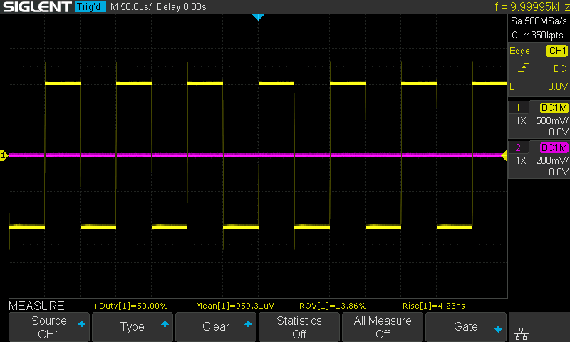 The screenshot Claude took during its run. The readouts along the bottom are measurements it added to the display (CH2 was on but unused).
What it didn’t do, and wasn’t asked to, is where the script still earns its place:
- It checked one way. Every number came from the scope’s own measurements, plus the screenshot. It never downloaded the samples, so
get_waveform, the path that had the signed-byte bug, was never used. Its answer couldn’t have found that bug. (The run used 2.0.2, which has the fix; the point is that nothing in its approach exercised that path.) - It left the output on. It said so plainly: “The generator output is still on.” I had asked it to generate a signal, so that’s a fair reading of the request. A test, though, has to end with the output off whatever happened.
- It didn’t put anything back. The scope stayed at the new settings, with its measurement readouts on the display. The script restores both instruments and reads them back.
In this run, the agent did well at the part that needs judgement: reading the measurements and explaining a number that looks wrong. The script is the part that has to be the same every time: two independent measurements, a known end state, and a clean bench. The script’s results are what the agent’s answer can be checked against, not the other way round.
What I took away
- Check against something that isn’t the system itself. A tool’s success message, a read-back and a unit test are all the system describing itself. A second instrument measuring the actual signal is not.
- Measure the same thing two ways. The bug showed up as a disagreement between the scope’s measurement and my analysis of the same samples. Either number alone looked fine.
- Tests written from the vendor’s documentation inherit its mistakes. My unit test asserted the bug as correct behaviour.
- When a test fails, check the test first. The 2.6 V square wave was ringing, not a fault.
- Let the agent interpret, and let the script decide. In one run, Claude explained the 2.6 V reading correctly, but with a one-sentence prompt it checked one way and left the bench as it was. The script checks two ways and always ends in a known state, whatever the prompt says.
- Tests with physical side effects need safe exit paths: refuse to start from an unknown state, switch the output on last and always off, restore what you changed, and say plainly when you couldn’t.
Try it
The loopback check is in the scope server’s repository. With a Siglent SDG generator connected to the scope’s CH1:
1
2
3
4
git clone https://github.com/MagnusJohansson/siglent-sds-mcp
cd siglent-sds-mcp
npm ci
npm run e2e-loopback -- <generator-ip> <scope-ip>
It runs a pinned version of the generator server from npm (2.0.6 at the time of writing; --sdg-version picks another) and the scope server from the repository. The get_waveform fix is in siglent-sds-mcp 2.0.1.
I wrote this post with Claude’s help, the same way I built the servers. The bench work, the decisions and the final check of every claim are mine.